Following the completion of carbon or graphite brick masonry in the blast furnace hearth, carbon-based monolithic materials are also required. The primary monolithic refractory materials utilized in the blast furnace hearth are carbon ramming mixes and carbonaceous injection mixes.
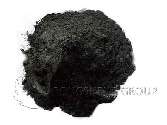
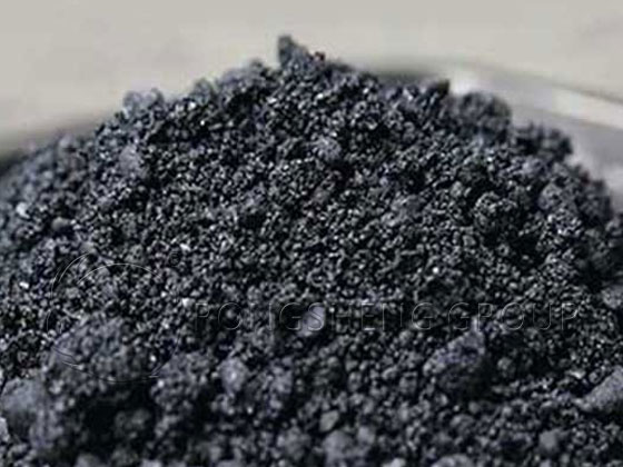
Carbon Ramming Mix
Carbon ramming mix is categorized into two types: that applied to the furnace bottom hearth plate and that applied to the furnace bottom sidewalls. This section outlines the properties of these carbon ramming mixes.
Furnace Bottom Carbon Ramming Mix
The structural design of a blast furnace bottom typically involves ramming a layer of carbon ramming mix onto the hearth plate, followed by laying carbon bricks or graphite bricks atop this rammed layer. The function of the carbon ramming mix on the hearth plate is primarily to provide a leveling layer; since the metal components of the hearth plate are prone to deformation, it is difficult to lay bricks directly upon them, necessitating the use of a rammed layer to create a flat, even surface. Because the direction of heat transfer (cooling) aligns with the direction in which the ramming mix is compacted, it is advisable to use a graphite ramming mix formulated with synthetic graphite—which exhibits minimal directional anisotropy—and bonded with a resin binder. This specific type of ramming mix is preferred because it does not undergo shrinkage under load, thereby facilitating the subsequent laying of bricks upon it.
Furnace Sidewall Carbon Ramming Mix
For blast furnaces featuring a steel shell with external water cooling (i.e., water-cooled furnace walls), carbon ramming mix is packed into the space between the carbon bricks and the furnace shell. For blast furnaces equipped with vertical cooling staves, the carbon ramming mix is packed between the carbon bricks and the vertical cooling staves. Since the direction of heat transfer (cooling) in this application is perpendicular to the direction in which the ramming mix is compacted, a mix utilizing natural flake graphite—which possesses directional anisotropy—is generally employed. Because the graphite ramming mix in the sidewalls must be capable of accommodating the thermal expansion of the carbon bricks, it is essential that the material exhibits compressibility at high temperatures; consequently, a graphite ramming mix designed to undergo shrinkage (typically around 10%) under load is generally selected for this application. Operational results have demonstrated that, to ensure this requisite compressibility, the most effective approach is to utilize a carbon ramming mix formulated with a thermoplastic carbonaceous binder and primarily composed of flake graphite.
Carbon Injection Materials for Blast Furnace Hearths
Blast furnace hearth structures typically employ one of two cooling methods: a steel shell with water-spray cooling or a vertical cooling stave system. During the initial stages of furnace ignition, the thermal expansion of the hearth lining—as well as the differential expansion resulting from thermal fluctuations during operation—can create gaps between the carbon bricks and the graphite ramming mix, or between the graphite ramming mix and the steel shell (or vertical cooling staves). Such gaps compromise the hearth’s cooling efficiency. Furthermore, in blast furnaces utilizing vertical cooling staves, the castable refractory material packed between the staves and the steel shell may shrink due to dehydration, creating additional gaps; moreover, air leaking from the tuyeres into the backing layers can cause deformation of the steel shell. To address these issues, openings can be cut into the steel shell to allow for the injection of refractory materials from the furnace exterior. Since maintaining cooling capacity is paramount, it is essential to utilize injected refractory materials with high thermal conductivity. All such gaps are effectively sealed through the pressure-injection of specialized carbonaceous materials.
In the formulation of hearth injection materials, priority is placed on achieving both high thermal conductivity and excellent injectability. Consequently, these materials typically utilize artificial graphite as the primary aggregate and a thermosetting furan resin as the carbonaceous binder; the mixture is prepared via intensive mixing and then pressure-injected, with a maximum grain size carefully controlled to fall within 50% to 70% of the gap width being filled. To minimize the viscosity of the mixed injection material—thereby facilitating smooth injection—the optimal proportion of fine artificial graphite powder in the composition is typically maintained within the range of 20% to 30%.
Differences Between Hot Ramming and Cold Ramming of Carbon Ramming Mixes
Carbon ramming mixes are classified into two types: hot-ramming mixes and cold-ramming mixes. Both hot-ramming and cold-ramming carbon mixes are amorphous refractory materials composed of granular refractory aggregates and a binder; generally, the use of cold-ramming carbon mixes is recommended.
Prior to ramming, hot-ramming carbon mixes must be crushed and heated. The heating temperature is determined based on the uniform mixing temperature required for the finished material; once the heated carbon mix is free of hard lumps, it is ready for placement and ramming. During ramming, a heated ramming tool (hammer) must be used, ensuring the material temperature remains no lower than 70°C. When employing the hot-ramming method, the ramming head should be heated to a dull red glow, and the air pressure must not fall below 0.5 MPa. Successive layers of material should be offset at a specific angle, and the ramming process must be continuous to prevent stratification. At the interface between layers, the surface of the previous layer must be “roughened” or brushed with a binder before the next layer is laid down and rammed. During ramming, the tool should be applied in a linear, back-and-forth motion—overlapping each stroke by half to one-third of the tool’s width—and this process should be repeated 2 to 3 times.
When ramming cold-ramming carbon mixes—thanks to advancements in product processing technology—pre-heating of the material is no longer required. Furthermore, no on-site mixing is necessary during construction; the material can be poured directly into the designated application area and compacted using either manual or mechanical methods. As with the hot-ramming method, the ramming tool should be applied with a half-overlap technique. However, it is crucial to note that the thickness of each rammed layer must not exceed 100 mm, and ramming should continue until the layer is fully compacted (aiming for a reference compression ratio of 40–45%). If additional thickness is required, a second layer may be laid down and rammed. Before laying the subsequent layer, however, the surface of the preceding layer must be roughened to ensure a dense bond between the upper and lower layers. The air pressure used during ramming for the cold method is the same as that for the hot method: it must not be less than 0.5 MPa.
The fundamental difference between the hot-ramming and cold-ramming methods for carbon ramming mixes lies in the fact that the cold-ramming method represents a departure from the traditional, older hot-ramming process; this shift has resulted in improved working conditions for personnel and enhanced performance characteristics for the refractory lining.
Main Applications of Carbon Ramming Mixes Carbon ramming mixes are primarily utilized to fill the gaps situated between the carbon bricks of the blast furnace hearth and the hearth sealing plates, or between the hearth carbon bricks and the cooling staves. Additionally, they are employed for leveling purposes above the centerline of the hearth’s water-cooling pipes and for filling the spaces within the cooling staves. By completely filling every corner and even the minutest crevices, these materials ensure that there is absolutely no leakage of molten iron or furnace gas.
Al₂O₃-C Refractory Ramming Mixes for Iron-Melting Furnaces
Historically, tapholes in blast furnaces were lined using high-alumina-carbon monolithic refractories; these were later superseded by the more durable Al₂O₃-SiC-C refractory materials. However, Al₂O₃-C ramming mixes have continued to be utilized for lining iron-melting furnaces to this day.
The aggregates for Al₂O₃-C ramming mixes are primarily selected from materials such as corundum, sintered alumina, sintered bauxite clinker, and clay clinker. Carbon components—including pitch, coke powder, petroleum coke, carbon granules, and graphite—are incorporated into the mix, with the specific addition rate determined by the operational requirements.
To enhance the installation properties of Al₂O₃-C ramming mixes and to ensure the volumetric stability of the resulting linings during service, bonding clay is added to the formulation. This clay may be introduced either by co-milling it finely with the alumina aggregates or by directly blending it with the carbonaceous materials.
The binder for Al₂O₃-C ramming mixes may be selected from organic binders, inorganic binders, or a combination of both. Typically, inorganic binders such as phosphoric acid, phosphates, silicates, and sulfates are employed.
Regarding the performance characteristics of various Al₂O₃-C ramming mixes: as the Al₂O₃ content within the mix decreases, the corresponding slag resistance also tends to diminish. Nevertheless, field trials conducted on the hearth, well, and taphole linings of high-capacity iron-melting furnaces (rated at 30 tons per hour) have demonstrated that the service life of these Al₂O₃-C ramming mixes is comparable to that of the more commonly used electrofused Al₂O₃-C ramming mixes.