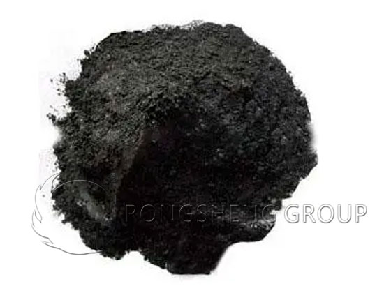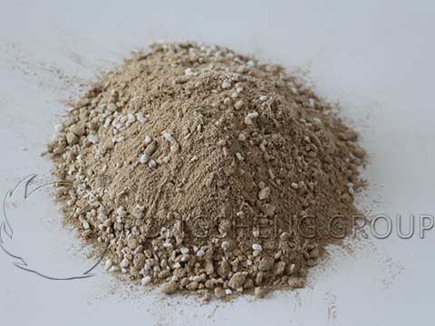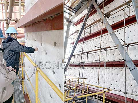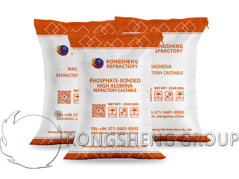
Currently, the working linings of high-power and ultra-high-power electric arc furnaces are generally constructed using dry-type magnesia ramming mixes. These mixes are formulated with a multi-stage particle size distribution, utilizing iron-rich, calcium-rich synthetic magnesia and fused magnesia as aggregates, along with synthetic and fused magnesia fines (with a maximum particle size of 5–6 mm). Dicalcium ferrite—derived from the synthetic magnesia component—acts as a sintering aid; no additional binders are required. The material is applied via intensive ramming to ensure high density. Upon heating to the appropriate temperature, it sinters into a solid, monolithic structure, offering a service life several times longer than that achieved through traditional ramming or brick-lining methods. Typically, a single application of a dry-type ramming mix can last for over 300 heats, with the potential to extend this to 500–600 heats through hot repairs. This not only reduces the frequency of furnace downtime but also significantly lowers the consumption of refractory materials per ton of steel produced.

Installation of Dry Ramming Mass for Electric Furnace Hearths
Preparation
Clean the permanent lining layer to remove all debris, such as slag, dust, wire, and plastic sheeting. Calculate the required ramming thickness by multiplying the target thickness by a factor of 1.09, and ensure an adequate quantity of ramming mass is prepared based on the dimensions of the furnace hearth and slopes. Upon arrival, inspect the material for foreign objects or moisture; remove any debris, and discard any material that has become damp. Prepare the necessary installation tools, such as mechanical rammers and pneumatic picks.
Installation Method
Spread the material evenly using a shovel, then compact it by foot to remove trapped air. After initial compaction, insert a steel rod into the material, wiggle it repeatedly, and then compact the area again by foot. Each layer of ramming mass should be 150–200 mm thick. Use the ramming tools to compact each layer, working in a spiral pattern from the perimeter toward the center; repeat this process three times. To verify the quality of the compaction, place a 5 mm diameter steel rod on the rammed surface and apply 10 kg of pressure; the rod should sink no more than 30 mm. Alternatively, during on-site installation, a steel rod can be driven into the material with force—it should not penetrate deeper than 30 mm.
The furnace slopes are installed using the same method as the hearth: first compact by foot, then use ramming tools. The angle of the furnace slopes should not exceed 40° to prevent the material from rolling or collapsing. In areas subject to intense agitation and erosion—such as around the taphole brick and the furnace door—the material should be rammed more vigorously, and the thickness may be increased to extend the service life of the refractory lining in these high-wear zones. Once installation is complete, cover the rammed surface with thin steel plates (5–10 mm thick) to prevent the hearth profile from being damaged during scrap charging, or to stop scrap metal from piercing the rammed layer, which could lead to a breakout. If steelmaking cannot begin immediately, place a 100–200 mm thick layer of lime over the steel plates to prevent the ramming mass from hydrating.
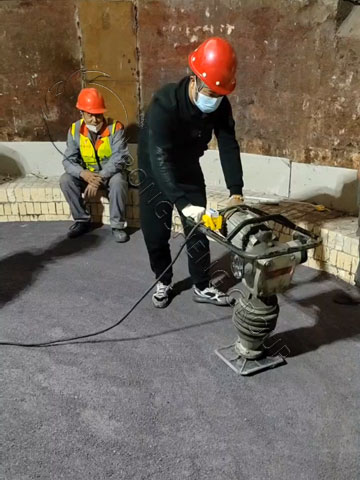
Operational Requirements for Smelting in a New Furnace
After the magnesia-calcia-iron synthetic ramming mix has been installed in strict accordance with technical specifications, it achieves a specific rammed bulk density. To ensure that this dry ramming mix sinters into a solid, monolithic structure during the smelting process—thereby enhancing its resistance to erosion by molten steel and corrosion by slag—the smelting operation of the very first heat in a new furnace is critical. The process should be carried out according to the following steps:
Charging Scrap Steel: Select high-quality scrap steel with low carbon (C) and silicon (Si) content; sheared scrap or small-sized pieces are preferred. The number of charging cycles should be one more than that used in standard smelting operations. During charging, the hopper should be positioned as close to the furnace bottom as possible to prevent large pieces from damaging the bottom lining. Subsequent charges should be added once approximately 80% of the previous charge has melted. Once all scrap has melted, the temperature should be raised gradually to above 1600°C and maintained at that level for at least 30 minutes.
- Smelting Rate: The smelting duration for the first heat should be 2 to 3 times longer than that of a standard heat. Use the lowest power setting possible, and the use of oil-oxygen or carbon-oxygen lances for assisted melting is strictly prohibited.
- Degassing/Venting: Once the scrap is completely molten—and particularly if the dust extraction system’s suction is insufficient—the operator should implement two degassing/venting periods, each lasting at least 30 minutes. During this time, maintain the temperature and tilt the furnace toward the taphole to ensure that the ramming mix surrounding the taphole area is thoroughly sintered.
- Oxygen Lancing: If the molten steel composition fails to meet requirements during the final stages of smelting, oxygen lancing may be necessary. In such cases, a “shallow” lancing technique is recommended: the oxygen lance should be inserted into the molten steel to a depth of approximately 100–150 mm at an angle of about 30°. The duration of this operation should be kept to a minimum to prevent damage to the furnace bottom lining caused by excessive oxygen flow or an improper lancing angle.
- Smelting Temperature and Duration: The smelting temperature for the first heat should be kept as high as possible, and the duration should be 2 to 3 times (or more) that of a standard heat. This facilitates the thorough sintering of the ramming mix at the furnace bottom. During tapping, a certain amount of molten steel should be left at the bottom of the furnace—a practice known as “retaining steel”—to protect the furnace bottom. Throughout the entire smelting process, care must also be taken to prevent the molten steel from boiling violently, which could cause erosion of the ramming material lining the furnace bottom.
Precautions for Using Dry-Ramming Refractory Materials in Electric Furnaces
- (1) Residual steel and slag on the furnace bottom must be thoroughly cleaned. Failure to do so can lead to delamination between the new and old material, potentially causing the rammed lining to heave or lift during operation, which reduces its service life.
- (2) During the ramming process, strictly follow all construction specifications to ensure the material reaches the required density. Inadequate compaction will cause significant shrinkage during operation, leading to extensive cracking and spalling, thereby shortening the lining’s lifespan.
- (3) The first heat (melt) is critical. When blowing oxygen for decarburization, ensure the oxygen lance is not inserted too deeply; otherwise, it may cause the rammed material on the furnace bottom to heave, resulting in the formation of large pits.
- (4) For the first heat, a layer of lime can be spread over the furnace bottom. This prevents scrap steel from directly impacting the bottom, protects the rammed material from hydration, and facilitates the early formation of slag.
- (5) If large pits form on the furnace bottom, all residual steel and slag must be completely removed before patching with fresh ramming material. If a small amount of molten steel remains in a pit, add lime or dolomite, then use an iron rake to clear out the mixture of dolomite and molten steel. Failure to do so will create an interlayer within the patch, compromising the effectiveness of the repair.

Insights into Dry Ramming Mixes for Electric Arc Furnace (EAF) Hearths
Currently, the working linings of high-power and ultra-high-power electric arc furnaces (EAFs) are predominantly constructed using magnesia-based dry ramming mixes. As the working lining, this refractory material comes into direct contact with molten steel and slag, enduring high thermal loads, slag erosion, the scouring action of molten steel, mechanical impact from scrap metal, and oxidation-reduction reactions at high temperatures. These conditions can lead to slag penetration into the hearth, causing the lining to thin. Furthermore, during intermittent (non-continuous) operations, dicalcium silicate (Ca2SiO4) present in the slag can absorb atmospheric moisture, causing the material to disintegrate and spall, which reduces its durability and overall service life.
Typical dry ramming mixes utilize synthetic magnesia (with high iron and calcium content) and fused magnesia as aggregates, with the same materials used in fine-powder form. The maximum particle size is generally 5–6 mm. Dicalcium ferrite (C2F) within the synthetic magnesia acts as a sintering aid; no additional binders are used, and the material is formulated using a multi-stage particle size distribution. Through intensive ramming, the required density is achieved, allowing the material to sinter into a solid, monolithic structure at appropriate operating temperatures. This approach offers a service life several times longer than traditional ramming or brick-laying methods.
Under standard operating conditions, a single application of a dry ramming mix can last for over 300 heats. Through hot-repair procedures, this can be extended to 500–600 heats, with some high-performance products on the market capable of exceeding 600 heats.
After a period of use, the EAF hearth may sustain varying degrees of damage. Consequently, the electric furnace refractory lining must be repaired based on the extent of the wear or damage.
- (1) Hot repairs are performed periodically during the smelting process. However, after every heat (following the tapping of steel and slag), the condition of the hearth must be carefully monitored; any depressions or pits exceeding 150 mm in depth must be repaired.
- (2) Before repair—which should be carried out immediately after tapping the steel and slag—the damaged surface must be cleaned using an oxygen lance to thoroughly remove any residual steel or slag.
- (3) Lower the ramming mass into the furnace, positioning it above the area requiring repair; maneuver the crane to ensure the material is distributed appropriately.
- (4) Use iron blocks or other heavy objects to compact the material.
- (5) It should be noted that for large-scale hot repairs to the furnace bottom or slopes—in order to ensure a longer service life, reduce the frequency of repairs, and lower the consumption of dry ramming mass per ton of steel—the first heat of steel following the hot repair should be processed in accordance with the operational requirements for a new furnace.