As an advanced type of firing equipment, the shuttle kiln has found widespread application in various sectors: in the machinery industry—specifically in plants producing electrical ceramics and grinding wheels; in the building materials industry—within sanitary ceramics factories; and in other fields such as environmental protection and refractory materials. Characterized by low energy consumption, uniform temperature distribution, short firing cycles, a high degree of automation, and production flexibility, the shuttle kiln has driven transformative advancements in the firing processes of the aforementioned industries. By generating significant technical and economic benefits, it is gradually replacing and phasing out traditional downdraft kilns—and even tunnel kilns. With the continuous advancement of technology and the ongoing development of related industries, shuttle kilns that are even more energy-efficient and highly automated are poised to see increasingly widespread adoption.
Structural Characteristics of Shuttle Kilns
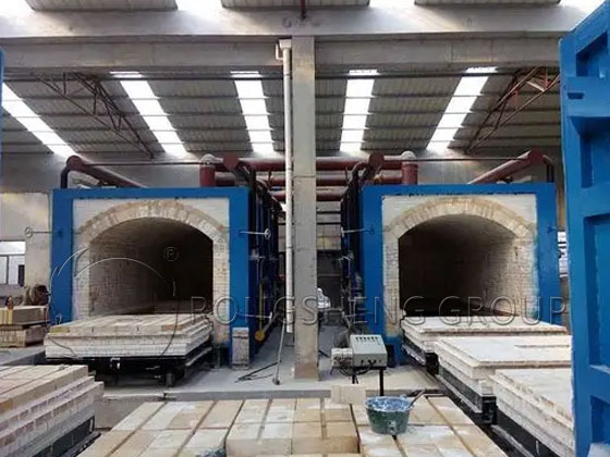
The structural form of a shuttle kiln resembles that of a car-bottom heating furnace or heat-treatment furnace; however, within the ceramics and refractory materials industries, it is specifically referred to as a “shuttle kiln.” As the name implies, the trajectory of the kiln car—as it is pushed into and pulled out of the kiln—resembles the movement of a “shuttle.” It is also sometimes referred to as a “drawer kiln,” a name likewise derived from the action of the kiln car being pushed in and pulled out. Since the shuttle kiln is a batch-type firing device, every firing cycle involves distinct heating and cooling phases. Consequently, the amount of heat stored and subsequently dissipated by the kiln body and the kiln car directly impacts the furnace’s thermal efficiency. Shuttle kilns predominantly utilize lightweight refractory materials to minimize heat storage and heat loss as much as possible. Simultaneously, they are equipped with temperature-regulating, high-velocity burners designed to prevent product defects that might otherwise arise from excessive temperature differentials between the flame and the products being fired. Furthermore, the turbulence and entrainment effects generated by the high-velocity airflow within the kiln serve to enhance convective heat transfer efficiency. The design fundamentally employs a flat-roof structure, ensuring that the kiln roof and side walls remain structurally independent; this allows for free thermal expansion and contraction, thereby facilitating the construction of a lightweight kiln body. At the same time, this design maximizes the utilization of internal kiln space. Additionally, shuttle kilns typically adopt a bottom-exhaust configuration, which creates favorable conditions for achieving uniform temperatures within the kiln and simplifies the layout of floor-level facilities within the workshop.
The aforementioned characteristics constitute the key factors that make shuttle kilns energy-efficient, capable of maintaining minimal temperature differentials, and conducive to short firing cycles; they also represent the critical aspects that distinguish shuttle kilns from standard heating furnaces and heat-treatment furnaces. Currently, the firing chamber volumes of commonly used shuttle kilns vary widely—ranging from as little as a few cubic meters for small units to nearly 200 cubic meters for large ones—and are not bound by a fixed standard series, but rather determined entirely based on the specific requirements of the user. The following section outlines the structural characteristics, design requirements, and construction specifications applicable to large-volume shuttle kilns.
A large-scale shuttle kiln typically comprises several major components, including the furnace steel structure, the refractory lining of the kiln body, the kiln door opening and closing system, the kiln car, the car entry and exit system, the furnace foundation (including the foundations for both internal and external tracks), the flue system, the combustion system, the exhaust system, and the control system.
Shuttle Kiln Structure
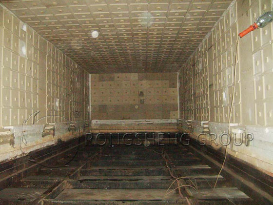
The refractory structure of a shuttle kiln typically consists of the following components: the kiln walls (both above and below the kiln car deck), the kiln door, the kiln roof, and the kiln car deck itself. Typically, the kiln walls situated below the car deck are constructed using heavy-duty refractory bricks, while the remaining three components are built using lightweight refractory materials characterized by excellent thermal shock resistance and low thermal conductivity and expansion coefficients. Depending on the specific operating temperature, the kiln’s firing chamber is constructed using various combinations of high-strength lightweight bricks paired with insulating fiber materials, or by utilizing composite refractory fiber modules—such as those made from polycrystalline mullite.
Refractory Materials for Shuttle Kiln Structures
The refractory materials for the kiln walls and roof are secured to the kiln’s steel structure using specialized structural configurations. Consequently, the steel structure of the kiln body must possess sufficient strength and rigidity to serve as a supporting framework. Typically, depending on the height of the kiln, the steel structure consists of vertical columns fabricated from various specifications of structural steel (most commonly I-beams or square steel tubes), wall panels made from steel plates of varying thicknesses (δ = 4–6 mm), and horizontal beams selected according to the kiln’s width. Additionally, most shuttle kilns are equipped with an operating platform.
Taking shuttle kilns in the electrical porcelain industry as an example, the refractory lining for the kiln walls typically consists of a composite structure comprising two layers of lightweight bricks combined with an insulating layer. This structure generally takes one of two forms: lightweight mullite bricks (300–348 mm) backed by aluminum silicate refractory fibers (80–100 mm), or lightweight mullite bricks (230 mm) backed by lightweight high-alumina bricks (114 mm) and aluminum silicate refractory fibers (80–100 mm). A very small minority of electrical porcelain shuttle kilns also utilize kiln wall and roof structures composed entirely of refractory fibers. Currently, refractory fiber products—after undergoing repeated cycles of heating and cooling, as well as exposure to high-velocity airflow—are prone to significant shrinkage, accelerated aging, and, most critically, fiber pulverization and spalling. In the context of shuttle kilns used for firing electrical porcelain and ceramic products, the occurrence of such issues leads to defects in both the appearance and performance of the finished products—a consequence entirely distinct from the heating objectives associated with metal heating or heat-treatment furnaces. Once fiber pulverization and spalling begin, the problem is extremely difficult to eradicate. Therefore, when selecting refractory materials for the kiln bodies of ceramic and electrical porcelain shuttle kilns—where strict requirements regarding product appearance are in force—extreme caution is exercised.
For kiln walls constructed from a combination of lightweight bricks and refractory fibers, a “floating anchor” structural system is employed to establish connections between the refractory bricks and the steel plates of the kiln wall, thereby serving as a measure to ensure the structural stability of the wall.
When constructing the walls, roof, and doors of a shuttle kiln using lightweight mullite bricks, air-setting refractory mortar is typically utilized for the masonry work. This mortar is required to possess excellent masonry properties—specifically, it must ensure an appropriate working time (or setting time), which is generally specified to fall within the range of 90 to 120 seconds. Furthermore, it is required that the material undergo a curing period following application before hardening begins, thereby developing excellent bonding strength at ambient (or low) temperatures (specifically, a minimum strength exceeding 0.5 MPa). Additionally, the material must be available in various specifications capable of meeting operational requirements within the temperature range of 1000°C to 1600°C.
Lightweight refractory bricks utilized in shuttle kilns are required to exhibit excellent thermal stability, demonstrate minimal linear shrinkage upon re-firing at safe operating temperatures, and meet specific performance criteria regarding thermal conductivity. These lightweight insulating refractory bricks are widely employed across industries such as electrical porcelain, general ceramics, and refractory materials manufacturing.
At the location of each flue along the kiln’s side walls, a series of high-velocity burners—designed for temperature regulation—are arranged in a vertically staggered pattern. The high-speed jet of combustion gases emitted by these burners serves as both the primary heat source for the shuttle kiln and the driving force behind the turbulent mixing and entrainment of the kiln atmosphere. The burner arrangement in shuttle kilns differs significantly from that of typical industrial furnaces, where burners are generally positioned in the lower sections of the furnace walls. Within a shuttle kiln, particular emphasis is placed on ensuring the simultaneous existence of airflow circulation in both the vertical cross-section and the horizontal plane; this dynamic is absolutely essential for achieving uniform temperature distribution throughout the kiln.
The doors of commonly used large shuttle kilns consist of a steel structure and lightweight refractory materials. Typically, the refractory lining is composed of lightweight mullite bricks (230–270 mm) backed by aluminum silicate refractory fibers (30–80 mm), with the entire door weighing between 3 and 6 tons. There are three primary mechanisms for opening and closing these doors: rotary, sliding, and lifting types. The kiln door body is suspended from an overhead beam and moves according to its specific opening/closing mechanism. Currently, the vast majority of shuttle kiln doors—regardless of their specific closing mechanism—are operated by electric drives; only a very small number of manufacturers still rely on manual operation. A critical aspect of the design is ensuring an effective seal between the kiln door and the main kiln body.
The kiln car and its refractory deck masonry constitute the floor of the shuttle kiln; together with the kiln walls, roof, and door, they define the firing chamber. The kiln car itself consists of a steel frame, wheels, and the refractory materials built upon it. When selecting the structural configuration and materials for the kiln car deck, designers must consider both load-bearing capacity and enhanced thermal insulation, while simultaneously striving to minimize heat storage and heat loss within the car’s masonry structure. The widespread adoption of lightweight kiln cars has provided an effective means of reducing the thermal energy consumption per unit of fired product.
With the exception of a few shuttle kilns imported from abroad that utilize top-exhaust systems (primarily due to high groundwater levels at the installation site), the vast majority of large domestic shuttle kilns employ bottom-exhaust systems. Based on the principles of vertical gas flow distribution, inducing a downward flow of high-temperature gases within the kiln is a crucial prerequisite for ensuring temperature uniformity across the horizontal plane. Shuttle kilns are characterized by the strategic placement of high-velocity burners at both the upper and lower levels of the vertical cross-section; combined with the bottom-exhaust system, this structural feature is instrumental in achieving the temperature uniformity that enables rapid firing cycles. This design principle has been successfully validated in various industrial furnaces, such as the heat-treatment furnaces used in the mechanical engineering sector.
Since the kiln flues are typically situated beneath the kiln’s foundation slab, flues located in areas with high groundwater levels are often constructed as waterproof structures. Alternatively, to mitigate the potential adverse effects of groundwater on the flues, some kilns are designed with a system of multiple, dispersed, and relatively shallow flues. In instances where heat exchangers are installed within the flues, seepage wells are often incorporated along the deeper sections of the flue walls to serve as an auxiliary measure for groundwater control and waterproofing. The kiln foundation is constructed using concrete with a grade of C-15 or higher; depending on variations in soil conditions and bearing capacity, it is typically designed as a reinforced concrete structure. The kiln car tracks are installed atop this concrete foundation. Given the specific load conditions of a shuttle kiln, light rails with a specification of 22 kg/m or heavier are typically selected.