The construction process of glass melting furnace is generally to first lay the bottom flue and heat storage chamber, and then lay the bottom, wall and breast wall bricks of the large kiln.
(1) Flue
When laying the top layer of bricks at the bottom of the flue, it should be perpendicular to the airflow direction, and the masonry should be started from the middle of the flue and carried out at both ends. When laying the flue, an expansion line of about 10mm is left for every 3m of straight line length, and it is staggered up and down, inside and outside. The masonry around the air exchanger should be inlaid after the gate frame is installed and inspected and qualified.
(2) Heat storage chamber
1) The outer wall of the heat storage chamber requires staggered laying of bricks of different types, and no straight joints of clay bricks (insulation bricks) and red bricks are allowed between two adjacent rows horizontally. One row is laid every 4 to 5 rows. The outer surface of the wall should be close to the I-beam column.
2) The partition wall of the heat storage chamber should be laid with staggered joints. Expansion joints are left at the door stacks of the heat storage chamber at both ends of the partition wall. Clay slurry is used for the clay brick part and silica slurry is used for the silica brick part. Mixing is strictly prohibited.
3) The heat storage chamber grate bars are not allowed to be skewed, and their spacing should be strictly kept accurate. The grate bar climbing (surface leveling) requires strict leveling.
When laying the heat storage chamber grate bars, first set the arch tire and then use the grate bar card plate to measure. Only after it meets the card plate can the grate be laid. The center line of the grate bar arch foot surface should be on the same straight line.
4) When building the door arch of each small furnace and heat storage chamber, first support the arch tire and then use the furnace bar to check the quantity. Only when it meets the card plate can it be built, and the semi-circular arch bricks between the arch foot bricks are built, and then the door arch is built. The door arch lock brick is 30mm higher than the arch top, and grouting should be carried out after it is driven in.
5) The error between the actual center line and the designed center line of each small furnace and heat storage chamber should not exceed 5mm.
6) Before building the semi-circular arch, the semi-circular arch should be tested horizontally and vertically to check whether it is qualified to determine the size of the mud joint.
When building the arch, use the mortar brushing operation. After each brick is placed, it must be knocked tight with a wooden hammer to make it tightly combined. After each row of bricklaying is completed, it must be leveled with a horizontal plate. When building the arch, both sides should be built at the same time to prevent the arch tire from moving. The joints between the semi-circular arch and the door arch or the small furnace weighing horizontal arch should be processed in advance, pre-built and numbered, and built according to the numbers when building. The lock bricks of the semicircular arch should be 50~80mm higher than the arch top. The lock bricks on the arches must be at the same angle and hammered in at the same time, and then grouting is carried out.
7) The weighing horizontal arch of the small furnace should be built in a circle, and its lock bricks should be 50mm higher than the arch top, hammered in together with a wooden hammer, and then grouting is carried out. The small furnace can be built after the column tie rods of the heat storage chamber are tightened and the arch bricks leave the arch tire.
8) The stacking of lattice bricks requires vertical and horizontal, the error of the center line of each grid hole shall not exceed 5mm, the error of the grid hole size shall not exceed 6mm, and the horizontal error of the upper surface of the lattice brick shall not exceed 8mm. When leveling the lattice bricks, it is strictly forbidden to use asbestos and other materials to solve the problem.
9) The holes for blowing in the heat storage chamber sealing wall must be left facing each longitudinal grid hole and closed with a race brick.
10) When laying the heat storage chamber wall, clay bricks must be laid between the grate arch foot, the semicircular arch and the outer wall reinforcement iron parts.
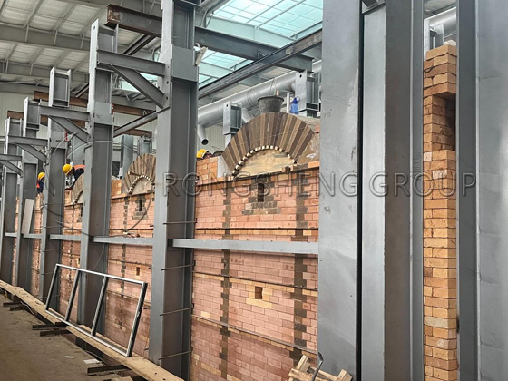
(3) Small furnace
1) The center lines of the small furnace ascending path should be laid out according to the design standards, and the error should not exceed 5mm. The center lines of each pair of small furnaces should overlap with each other, and the error should not exceed 10mm. The center line of the small path should be strictly perpendicular to the center line of the kiln pool.
2) The cross-sectional dimensions must be accurate during masonry, and the four corners of the small furnace must be neat to facilitate the installation of the steel structure.
3) A 30mm expansion joint is left between the bottom of the small furnace neck and the front wall of the small furnace. Straw ropes are used to pad the joints during masonry, and then pulled out after masonry is completed.
4) The small furnace arch is always built with mortar.
5) When laying the small furnace arch and locking bricks, the arch foot angles on both sides should be fixed.
(4) Kiln bottom
1) Large clay bricks at the bottom of the melting furnace pool are required to be dry-stacked. They must be selected, processed and numbered in advance. Bricks that make a mute or cracking sound when knocked, have cracks or caves, and have a break of about 30mm on the outside and more than 10mm on the inside are not allowed to be used.
2) Except for the surface that contacts the glass liquid, the remaining surfaces of large clay bricks at the bottom of the melting furnace pool should be processed. The processed surface of the brick should be checked with a ruler and a square ruler. The gap between the ruler and the brick surface should not exceed 1mm.
3) The bottom of each part of the masonry should be stacked from the center line to both sides. The brick joints must be staggered with the flat steel at the bottom of the kiln. The bottom of the kiln should be stacked directly, horizontally and vertically parallel. Expansion joints should be left between bricks. The upper part of the gap should be clamped with horse manure paper of about 50mm to prevent broken bricks and glass from entering.
4) The pool bottom bricks must be leveled, especially the upper surface of the pool bottom where the pool wall is built must be measured and leveled to ensure that the entire kiln is strictly level.
(5) Pool wall
1) The electro-melting cast bricks for the pool wall should be weighed piece by piece, and the bricks with large volume should be used in the high-temperature and easily corroded parts of the melting part and the feeding pool, and the corners of the entrance of the neck.
2) The corners of the pool wall should be stacked into straight seams, and it is strictly forbidden to bite the slag. The straight seams should be parallel to the longer section of the pool wall.
3) The pool wall must be straight, and the casting mouth of the mullite or zirconium corundum bricks should face the pool. The brick joints must be tight, staggered up and down, and there must be no through seams, and the gap must not exceed 5mm.
4) The allowable error of the top surface elevation of the entire melting furnace pool wall does not need to exceed ±10mm. At the same time, the top surface elevation of the melting part pool wall should not be lower than the standard of the top surface of the pool wall in front of the liquid outlet.
5) After the pool wall, the pool bottom and its upper structure that are in contact with the glass liquid are all built, the inner surface of the masonry should be cleaned of dirt with a steel brush and blown clean with compressed air.
(6) Breast wall
1) When laying hook bricks and breast wall, measures should be taken to prevent them from tipping into the kiln. When placing hook bricks, pull a line through the cast iron plate to level and spread a thin layer of mud, tighten it with wooden wedges on the pool wall, and place the hook head on the wooden wedges to keep the hook surface level and prevent it from tilting into the kiln due to unstable center of gravity when laying the breast wall.
2) When the hook bricks are dry-stacked, the upper surface should be leveled with a level ruler. Leave a 1 to 1.5 mm expansion joint between each hook turn, pad the joint with horse manure paper, and pull it out after laying. However, no expansion joint is left between the hook bricks facing the I-beam column, and a 5 mm expansion joint should be left between the hook surface of the hook brick and the cast iron plate.
3) No expansion joint is left between the upper gap brick and the large arch. Each brick is hammered solid. The back of the upper gap must be clamped tightly. The contact surface between the small surface and the large arch corner is required to be sealed with mud, and the contact surface between the large surface and the large arch brick is required to leave a gap of 3~5mm.
4) The corundum breast wall casting mouth faces outward.
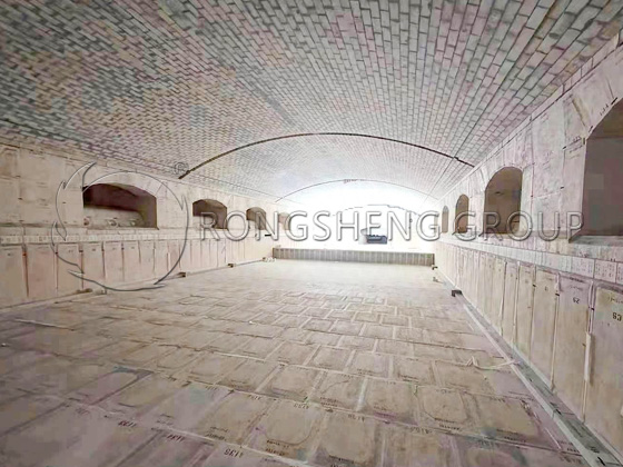
(7) Arch of the melting furnace
The construction of the arch is the most critical. The arch span of this melting furnace is 10800mm. The arch is built with 400mm thick silica bricks, weighing about 312.6t. This project adopts an insertable small furnace mouth (8 pairs in total), so there is no reverse arch on the arch.
Arch construction process: arch center line layout → arch brick pre-arrangement → masonry control line, each section expansion joint control line layout → arch brick stacking → arch brick masonry → arch brick locking → cleaning, grouting → tightening tie rods → jointing, cleaning.
1) Pre-arrangement
After the installation of the arch tyre is completed, carefully check and adjust the span, arch height, tread curvature and arch top elevation. First, the longitudinal center line and the expansion joint line of each arch brick are marked on the arch tyre to pre-arrange the arch bricks. During the pre-arrangement, a ring is pre-arranged at both ends of each arch section, and the size of the mortar joint is determined by the actual size of the on-site pre-arrangement. Install a pre-made large arc keel frame at the end of the arch and the expansion joint. This frame should be 20-30mm higher than the arch brick, so that it is convenient for pulling the wire.
2) Laying out the wires
In order to ensure the overall beauty of the large arch surface and no misalignment, a parallel control line is laid out according to the thickness of the arch bricks in 3 rings as the masonry reference line. The position of the temperature measuring hole brick is laid out based on the center line of the 1# small furnace. Control points are also popped out on the keels at both ends of each section. This point is the reference for pulling the wire on each ring of the arch brick surface. After the laying out work is completed, 1/5 of the bricks used for the entire large arch are stacked on the arch formwork, and the load-bearing condition of the arch formwork is observed. If there is no abnormality such as sinking, the masonry of the large arch can be started.
3) Masonry
Large arches are generally divided into 5 to 7 sections, each section is between 5 and 8 meters long. In order to ensure the overall quality of the column arch, masonry should be completed in a relatively short time to ensure that the bricks are locked before the mortar dries. It is not suitable to have too many people when masonry large arches. Generally, 6 technicians are arranged for each section. During construction, masonry should be symmetrical, and each row of arch bricks should be laid from both ends to the middle at the same time, and the speed should be consistent. There are 3 technicians on each side of each section, and each ring is masonry longitudinally, and the upper wire is drawn from both ends to the middle.
If bricks need to be processed, put the processed bricks in the middle, that is, the center of the column in the middle of each section, and the upper and lower rings should be staggered. The processed bricks cannot be less than 130mm.
It is strictly forbidden to put the big and small heads of arch bricks upside down during masonry. Each brick should be masonry, and the mortar fullness of the flat joints and top joints should reach more than 95%. Use a rubber hammer or a wooden hammer for correction. After each ring is built, use a card to check the angle of the arch bricks, and use a 4000mm aluminum ruler to check the flatness.
After 20 rings are laid on each side, the remaining number of rings is pre-arranged again. If there is no change, continue construction. When there are 15 rings in the middle, pre-arrange again. If there is any change, adjust. The last three rings are staggered and laid at the same time, leaving a ring of lock bricks. The lock bricks should be left in a ring off the center, so that it is convenient for the laying of temperature measurement hole bricks. The protruding part of the lock brick should be left at 100-120mm.
After the same section is laid, the lock bricks are driven in uniformly. When driving the lock bricks, a wooden board must be placed on the arch bricks, and the big wooden hammer cannot directly contact the arch bricks. After the entire arch is locked, clean the arch top and fill the seams with diluted mud. The allowable size deviation of the concentrated expansion joint of the arch is 0-+2mm, and the surface tooth misalignment of the arch brick is less than 2mm. After the kiln is baked, the large arch expansion joint is filled with silica bricks and silica hot patching materials.
4) Tightening the tie rods
Tighten the tie rods immediately after the arch is built. Before tightening the tie rods, remove the temporary fasteners on the steel parts and the wooden wedges on both sides of the breast wall. Tightening the tie rods is to make the brick body of the entire arch and the supporting steel structure become a whole. The amount of tightening data is determined by the size of the arch collapse, and is roughly controlled at about 1‰ of the arch span. Generally, the method of directly observing the changes in the arch crown is adopted to observe how much the arch crown bulges upward after being subjected to the horizontal tension of the tie rods to reflect the force of the arch crown.
Mark the measuring point positions near the tie rods at the head, middle and tail of each arch section, in the middle and on both sides of the arch section. Use a level and a ruler to measure the elevation value of the arch when the tie rods are not tightened at the measuring point, and then measure the changes in the elevation values of each measuring point every time the tie rods are tightened and record them until the arch value reaches the expected value.
When tightening the tie rod, use a special wrench and sleeve to tighten the nut from the arch head to the arch end one by one. Arrange operators at both ends of each tie rod to tighten the nut slowly at the same time and with the same force, but do not tighten it at one time, but repeat it back and forth. Rest for about 1 hour in the middle of each cycle until the arch is tightened and bulges upward, so that the ruler shows a reading.
Then proceed at a speed of 2mm per hour until it reaches 1‰ of the arch span. During the process of tightening the tie rod, if it is found that the size of the bulge on both sides of the arch is asymmetrical, temporarily fix the steel column on the side with the larger reading, tighten the tie rod nut on the side with the smaller reading, keep it symmetrical, and then remove the temporary fixings to ensure that the two sides of the arch brick are symmetrical and balanced until the arch brick is separated from the barrel wood mold. After tightening to the design value, keep it for 24 hours for observation until the value no longer changes, and then start to remove the mold after inspection and confirmation.
5) Remove the wooden formwork
Remove the wooden wedges under the columns, let the entire wooden formwork fall about 100mm, check the overall condition of the arch, and then use wooden strips to push up to separate the plywood and strips on the arch, and then remove the wooden formwork, clean it up and transport it out. Check whether there are arch bricks with broken corners, cracks, inversions, etc. on the lower arc surface of the arch. If there are any, they should be replaced in time, and then the joints should be pointed and cleaned. After inspection, the construction of the arch has met the design requirements, and then a comprehensive and thorough cleaning is carried out, and finally the bottom bricks of the pool are laid, and the exit is protected until the kiln is ignited.