The Taphole of the converter can be divided into machine pressing production and isostatic pressing production in terms of forming methods. The machine pressing tapping hole has a large volume density and high strength. The isostatic pressing tapping hole has a uniform structure and uniform internal stress distribution. It can be divided into split and integral tapping holes in terms of structure. The split tapping hole is easy to install, but due to the gaps in the product, it is easy to leak steel during use. The integral Taphole is heavy and inconvenient to install. However, since the product is a whole and has no gaps, it is not easy to leak steel. The choice of which production method or structure of the tapping hole should be considered comprehensively in terms of use and installation. The Taphole is generally composed of a tapping hole Well Blocks and a sleeve brick, also called a tube brick.
Well Blocks for Taphole
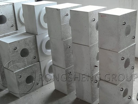
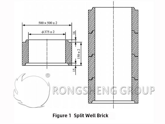
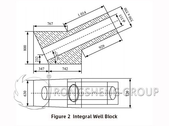
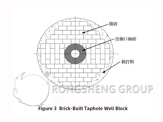
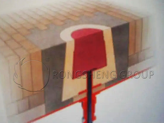
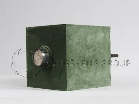
The Taphole Well Block is a brick that is placed outside the sleeve brick. Its function is to protect the sleeve brick and to support the converter brick when the sleeve brick is replaced and drilled so that the sleeve brick can be replaced easily. Common Well Blocks include pre-formed fixed products and those directly built on-site with bricks. Figures 1 and 2 are fixed products. Figure 1 is a split-Well Brick. Each Well Block has a mother-and-child platform and is assembled from one Well Block after another according to the total length of the tap hole. Figure 2 is an integral Well Block. It can be divided into two parts during production, and the two pieces are bonded together after production to form a whole and installed on the converter. Figure 3 is a brick-built Taphole Well Block built directly on-site with bricks. Comparing these Taphole seat bricks, the split and integral Taphole Well Blocks are pre-formed, so they can be directly installed after being assembled with the sleeve bricks during masonry, with fewer steel leakage channels and a high safety factor. Brick-built Taphole Well Blocks are generally built with working layer bricks in the converter shell. Other places are built on site with permanent layer magnesia bricks, and the surrounding is filled with ramming materials. The structure is relatively loose, with many steel leakage channels, but the cost is relatively low. The prefabricated steel outlet Well Blocks are generally square or round in shape, with round inner holes, and the size of the inner hole is 40-100mm of the outer diameter of the sleeve brick.
Taphole Sleeve Bricks
The Taphole sleeve brick is the channel for the molten steel in the converter to flow to the ladle. It is in direct contact with the molten steel, and its life directly affects the steelmaking rhythm of the converter. Structurally, the tap hole sleeve brick is divided into integral sleeve brick, also known as the Taphole pipe brick, and split sleeve brick. The integral sleeve brick is generally formed by isostatic pressing, and the split sleeve brick is formed by machine pressing. In order to facilitate installation on the converter, the Taphole sleeve brick is often assembled into one with a steel pipe and a flange.
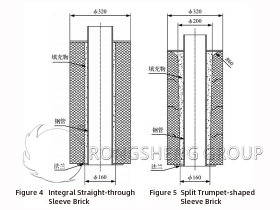
Whether it is an integral or split sleeve brick, the Taphole sleeve brick is generally circular in shape, and the inner hole is a circular structure of a through hole. The size of the inner hole is determined according to the tapping time, the wall thickness is generally 50-100mm, and the shape of the hole is divided into straight-through and trumpet-shaped. Experiments have shown that the tapping speed of the trumpet-shaped inner hole and the circular inlet shape is larger. This means that the interference between the molten steel and the Taphole is reduced, the water flow is relatively stable, and the circular inlet of the tapping hole shortens the tapping time. Figure 4 is an integral straight-through sleeve brick, and Figure 5 is a split trumpet-shaped sleeve brick.
Improvement of the Steel Outlet
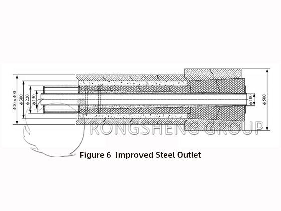
When assembling the conventional steel outlet Well Blocks and sleeve brick, there is a gap of 20-50mm between them, which is filled with ramming material or spraying material after assembly. If the ramming material or spraying material is of poor quality or not densely filled, it is easy to leak steel here. In order to eliminate the safety hazard of the gap, the gap between the Well Blocks and the sleeve brick is minimized. Figure 6 shows the improved steel outlet. As can be seen from the figure, there is still a large gap between the steel outlet Well Blocks and the sleeve brick in the converter according to the conventional design. The Well Blocks and sleeve brick away from the furnace are designed to be seamlessly matched. During installation, a thin layer of fire mud is applied to the outside of the sleeve brick. After assembly with the seat brick, the two are tightly matched, and there is no steel leakage channel, thus solving the steel leakage problem.
Masonry and Maintenance of Gas Supply Components | Air-permeable Bricks and Protective Sleeve Bricks for Converters
Gas supply components are key equipment for composite blowing. Starting from the metal tube nozzle, in order to protect the gas supply components, they are generally equipped with protective sleeve bricks, and the perfect ones are composed of a set of bricks. As shown in Figure 7. The construction of the bottom gas supply component refers to the construction of a set of combined bricks such as gas supply components and protective sleeve bricks at the bottom of the furnace. The life of the bottom gas supply component is not only related to its own structure, gas source, material, operating process and the material of the protective sleeve brick, but also to its masonry quality at the bottom of the furnace.
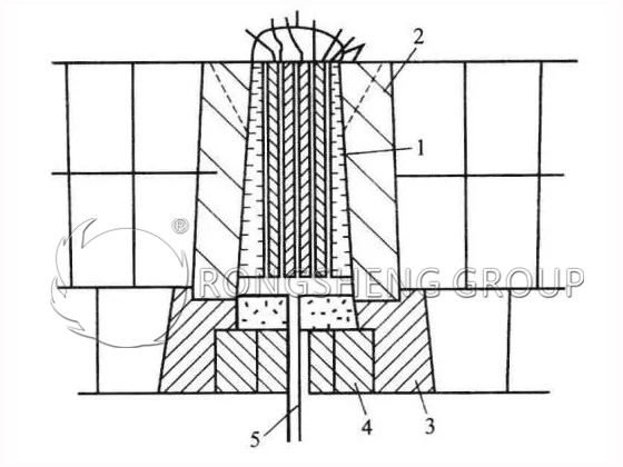
1-permeable component. 2-protective sleeve brick. 3-lower Well Blocks. 4-bottom brick. 5-steel pipe.
Due to the use of the gas supply element at the bottom of the furnace, the temperature of the refractory material around the element changes violently. In addition, the stirring force of the molten pool is strengthened, and the melting loss of the bricks at the bottom of the furnace, especially around the tuyere, is large. Therefore, in addition to the furnace bottom, refractory materials with peeling resistance, small expansion rate, small residual expansion, and good strength should be used. In addition, the method and quality of furnace bottom masonry are also very important to the life of the furnace bottom and gas supply elements. As the cross-sectional shape of the brick increases, the thermal stress also increases, which is easy to cause peeling loss. Therefore, small gas supply elements and mitigation elements are currently used. A comprehensive masonry method of expansion and contraction caused by temperature changes around and throughout the furnace bottom is used. If two elements are not built on the same line, the masonry needs to be tight. The gap between two adjacent bricks should be minimized, the top surface should be built flat, the bricks should be close to each other, and the edges should be tight. The working layer and the safety layer shall not be filled with knotting materials or refractory mixed powder. The gas supply element should be perpendicular to the furnace bottom, and the joint surface should be corrected to be horizontal after the furnace bottom is cut. The concave and convex should not exceed the standard requirements. At the same time, the built furnace bottom must be stored on a pad to prevent the pipe of the furnace bottom gas supply element from being pressed.
How to Maintain the Bottom Gas Supply Components?
Compared with top blowing, combined blowing and bottom blowing have strong stirring forces and low carbon monoxide partial pressure in the furnace. Therefore, good metallurgical properties are required. However, the furnace bottom life is low. The characteristics of furnace bottom loss of oxygen bottom blowing and combined blowing are as follows.
- ① The temperature of the refractory material around the component nozzle changes violently. The refractory material is affected by the drastic temperature change when blowing oxygen and not blowing, and the loss increases. The difference between the start-up temperature and the stop-blowing temperature is 200~400℃.
- ② Due to the backflow of the oxygen jet, the molten steel with high FeO concentration impacts the furnace bottom. The melting loss and wear of the refractory material at the furnace bottom are aggravated.
- ③ Compared with LD, combined blowing and bottom blowing strengthen the flow of molten steel, increase the flow rate of molten steel on the furnace bottom surface, and promote the loss of furnace bottom. The flow of molten steel is also affected by the arrangement of nozzles. On the furnace bottom with paired nozzles, the smaller the nozzle spacing, the greater the flow rate of molten steel on the furnace bottom surface. Therefore, the wear on the furnace bottom is also greater.
If only inert gases such as N2 and Ar are sprayed, the loss caused by the flow of molten steel will be small. The temperature change of the refractory materials around the nozzle is also small, and the loss caused by FeO is also smaller than the bottom blowing method. However, the erosion of the furnace bottom is generally more serious than that of the top blowing due to the presence of bottom gas. The structure, material selection, molding, assembly, masonry and process of the bottom gas supply components all have an impact on their life.
For metal sleeve type nozzles, reasonable structural assembly, maintaining uniform and unobstructed annular gap spacing, appropriate cooling protection, and reasonable gas supply intensity and use maintenance are the key to improving life. Among them, the control of the cooling medium used for cooling protection is crucial.